UML: Creating Sequence Diagrams
Contributed and maintained by Cindy Castillo, Bob May
November 2007 [Revision number: V1-4]
This publication is applicable to NetBeans IDE 6.0 and 6.1 releases.
In this tutorial, you learn how to use the UML features of the IDE to create a UML Sequence diagram. A Sequence diagram is a visual representation of the interaction between collaborating groups of objects in a system. Sequence diagrams consist of vertical lines called lifelines. Each Lifeline element represents the life of a given object. Lifelines are connected by horizontal lines denoting messages that pass from one object in the scenario to the next object in the scenario. .
Expected duration: 30 minutes
Tutorial Requirements
Before you proceed, make sure you review the requirements in this section.
Prerequisites
This tutorial requires that you complete the companion tutorials that create a Class diagram and a Collaboration diagram using the UMLTutorialProject. Complete UML: Creating Class Diagrams and UML: Creating Collaboration Diagrams before starting this Sequence diagram tutorial.
To use this tutorial, the IDE must be installed on your system and you should be familiar with the basic parts of the IDE. You should also have a basic familiarity with the Java programming language and UML. For a basic understanding of the IDE, see the IDE Basics topics in the online help. A good resource for UML techniques and theory is the official UML resource page at http://www.uml.org/
Software Needed for This Tutorial
To follow this tutorial, you need the software and resources listed in the following table.
top
Using Sequence Diagrams
A Sequence diagram is a model that describes how groups of objects collaborate in some behavior over time. The Sequence diagram captures the behavior of a single use case and shows the objects and the messages that are passed between these objects in the timeframe of the specific use case. The Sequence diagram does not show relationships between objects.
The Sequence diagram may be used to:
- Describe the overall sequence of the flow of control when there are many short methods in different classes
- Show concurrent processes and activations
- Show time sequences that are not easily depicted in a Collaboration diagram
- Show general forms that do not deal with objects but with class interaction
top
Creating Sequence Diagrams
This tutorial uses the Class diagram that is created in the tutorial UML: Creating Class Diagrams and the Collaboration diagram that is created in the tutorial UML: Creating Collaboration Diagrams. You should complete these tutorials before proceeding with these steps.
This section contains the following procedures:
top
To Generate a Sequence Diagram
- If necessary, start the IDE.
- In the Projects window, right-click the UMLTutorialProject > Model > CollaborationDiagram node and choose Create Diagram From Selected Elements from the pop-up menu.
The New Wizard opens and displays the Create New Diagram page.
Note: You are scoping one of the two types of interaction diagrams available from the pop-up menu: Collaboration Diagram and Sequence Diagram. These diagrams emphasize object interactions.
- In the Diagram Type list, select Sequence Diagram.
- In the Diagram Name field, type SequenceDiagram.
- Leave the default setting in the Namespace field and click Finish.
The IDE does the following:
- Creates the SequenceDiagram node under the CollaborationDiagram node in the Projects window
- Displays the new diagram in the Diagram editor (the diagram consists of Lifeline elements and messages from the Collaboration diagram)
- Opens the Modeling Palette and displays icons used in creating Sequence diagrams
Your diagram should resemble the following figure.
top
To Refine the Generated Diagram
Objects in a transaction are drawn as dotted vertical lines with the names showing at the top. Because the order of the Lifeline elements can not be predefined when the Sequence diagram is created, you need to reorder them at this time.
- Select the Lifeline labeled User and move it to the left of the diagram.
- Reorder the remaining Lifeline elements by placing them evenly across the Diagram editor. Put the Lifelines in the following order from left to right:
- User
- ATM
- Consortium
- Branch
Your diagram should now resemble the following figure.
top
Adding a Message to Self Element
A Message to Self diagram element represents a message intended for the calling object. The internal operation represented in this diagram is the validation of the cash on hand in the ATM object.
- You may need to lengthen the Lifeline elements to ease the placement of the Message elements.
To lengthen the Lifelines, follow these steps:
- Select the User Lifeline element.
- Click the blue box at the bottom center and drag the box downward to lengthen the Lifeline.
- Repeat steps a and b to lengthen the remaining Lifelines until your diagram resembles the following figure.
- From the Basic section of the Modeling Palette, select the Message to Self icon
 .
.
- Click the lower section of the extended ATM Lifeline element.
The IDE places a Message to Self element on the Lifeline.
- Right-click anywhere in the Diagram editor to deselect the Message to Self icon.
- On the Message to Self element, click the lower message arrow.
The properties for the message appear in the Properties window.
- In the Properties window, in the Name field, type validateCashOnHandOperation and press Enter.
- Right-click the upper message arrow on the Message to Self element and select Operations from the pop-up menu. The following figure indicates where to position the cursor. Note the double bar just above the top arrow.
- Choose Operations > Add Operation from the pop-up menu.
A one-line editor opens and displays the following information:
visibility returnType name(parameter) {properties...}
- Define your operations to be as follows
public boolean getIsOperating()
The upper portion of the message is labeled as shown in the following figure.
top
Using the Call Message Element
Because the validateCashOnHand operation is part of the ATM class, you need to place a message flow on the Lifeline to call that operation.
- From the Basic section of the Modeling Palette, select the Synchronous Message icon

- Click on the User Lifeline element, just below the
getCashOnHand() message.
- Click again on the ATM Lifeline element directly to the right of your first click.
A message and a return message appear on the diagram as shown in the following figure.
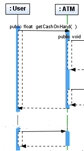
Note: If you do not want the return message to appear on the diagram, right-click in the white space of the Diagram editor. Deselect Show All Return Messages from the pop-up menu.
- Right-click anywhere in the Diagram editor to deselect the Synchronous Message icon.
- Right-click the message you just created and choose Operations > Add Operation from the pop-up menu.
- Type validateCashOnHand and press Enter.
The IDE labels the message on the diagram and adds the message as an operation in the ATM class in the Class diagram. In the Projects window, expand the ATM class node to verify that the list of operations resembles the following figure.
top
Using the Auto-Expand Messages Option
To help in the design process, the IDE has an option to auto-expand messages. With auto-expand selected, when a new message is placed on the diagram, the space expands to the width of the message.
- In the gray header area above the lifelines elements, right-click in the area between the User and ATM element names to set the auto-expand option.
A pop-up menu opens.
- Select Set Width to Message Width.
An indicator bar appears in the track between the two element names as shown in the following figure.
- Repeat the steps to set the message width option between the ATM and Consortium elements and between the Consortium and Branch elements.
top
Using the Create Message Notation
The Create Message notation enables the creation of a Lifeline element or instance.
- From the Basic section of the Modeling Palette, select the Create Message icon
 .
.
- Click the lower portion of the Branch Lifeline.
- Draw the link to the right of the Branch Lifeline and click again.
A message and a lifeline are placed on the diagram as shown in the following figure.
- Press the ESC key to deselect the icon.
- Select the new Lifeline.
The Properties window displays the properties for this Lifeline element.
- In the Properties window, on the row labeled Representing Classifier, click the down arrow.
A drop-down list appears.
- Select CashierStation from the drop-down list and press Enter.
- Click in the Diagram editor to see the labeled Lifeline element.
Your diagram should resemble the following figure.
top
Adding Asynchronous Links
An asynchronous message element represents a message that does not block the calling object. This kind of message is capable of creating a new object, creating a new thread and communicating with an existing thread.
- From the Basic section of the Modeling Palette, select the Asynchronous Message icon
 .
.
- Draw a link between the Branch and CashierStation Lifelines by clicking the Branch Lifeline element, then click the CashierStation Lifeline element.
- Press the ESC key to deselect the icon.
- Right-click the new link and choose Operation > public int getStationID from the pop-up menu.
This action adds the operation to this message as shown in the following figure.
top
Using the Combined Fragment Element
The combined fragment lets you express logical components, such as alternatives, options, exceptions, parallel merges, loops, negations, critical regions and assertions directly on your Sequence diagram. Combined fragments provide a means to define special conditions and subprocesses for any sections of any lifelines by specifying an area where the condition or subprocess applies.
- From the Control section of the Modeling Palette, select the Combined Fragment icon
 .
.
- To draw the Combined Fragment element so that it encapsulates the message, public void validateCashOnHand, click outside the blue dotted rectangle representing the message and click and drag the rectangle to surround the message.
Be careful that you do not select any of the Lifeline elements when you click. Your Combined Fragment should look like the following figure.
- Press the ESC key to deselect the icon.
- Right-click the assert label in the Combined Fragment element and choose Interaction Operator > loop.
Note: A loop Interaction Operator designates that the Combined Fragment represents a loop. Each time the loop repeats, the guard expression is evaluated. The guard expression can include a specific number of iterations of the loop.
- Right-click the Combined Fragment label loop and choose Interaction Operand > Edit Interaction Constraint from the pop-up menu.
The IDE displays an expression box in the target Combined Fragment element.
- Double-click the word expression to make the expression box editable as shown in the following figure.
- Type x < 10 and press Enter.
- Click in the Diagram editor.
Your expression is accepted and displayed in the box. Your diagram should resemble the following figure.
top
Saving Your Diagram
After you have completed your Sequence diagram, you can save it.
- In the Diagram editor, right-click on the SequenceDiagram tab.
- Select Save Document from the pop-up menu.
The menu closes and the diagram is saved.
Note: You are also prompted to save or discard your diagrams when you exit from the IDE.
top
Summary
In this tutorial, you learned to create a Sequence diagram using an existing Collaboration diagram. You learned how to perform the following tasks:
- Generate a Sequence diagram from an existing Collaboration diagram
- Add Messages to the diagram using icons from the Modeling Palette
- Add Links to the diagram
- Add a Combined Fragment element
- Save the diagram
top
Next Steps
To send comments and suggestions, obtain support, and stay informed of the latest
changes to the NetBeans IDE J2EE development features, join the nbusers@netbeans.org
mailing list.
top
